As far as I understand the serial port so far, transferring data is done over pin 3. As shown here:
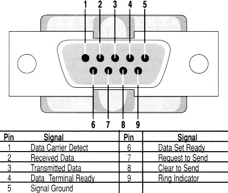
There are two things that make me uncomfortable about this. The first is that it seems to imply that the two connected devices agree on a signal speed and the second is that even if they are configured to run at the same speed you run into possible synchronization issues... right? Such things can be handled I suppose but it seems like there must be a simpler method.
What seems like a better approach to me would be to have one of the serial port pins send a pulse that indicates that the next bit is ready to be stored. So if we're hooking these pins up to a shift register we basically have: (some pulse pin)->clk, tx->d
Is this a common practice? Is there some reason not to do this?
EDIT
Mike shouldn't have deleted his answer. This I2C (2 pin serial) approach seems fairly close to what I did. The serial port doesn't have a clock开发者_运维知识库 you're right nobugz but that's basically what I've done. See here:
private void SendBytes(byte[] data)
{
    int baudRate = 0;
    int byteToSend = 0;
    int bitToSend = 0;
    byte bitmask = 0;

    byte[] trigger = new byte[1];
    trigger[0] = 0;

    SerialPort p;
    try
    {
        p = new SerialPort(cmbPorts.Text);
    }
    catch
    {
        return;
    }

    if (!int.TryParse(txtBaudRate.Text, out baudRate)) return;
    if (baudRate < 100) return;
    p.BaudRate = baudRate;

    for (int index = 0; index < data.Length * 8; index++)
    {
        byteToSend = (int)(index / 8);
        bitToSend = index - (byteToSend * 8);
        bitmask = (byte)System.Math.Pow(2, bitToSend);

        p.Open();
        p.Parity = Parity.Space;
        p.RtsEnable = (byte)(data[byteToSend] & bitmask) > 0;

        s = p.BaseStream;
        s.WriteByte(trigger[0]);

        p.Close();
    }
}
Before anyone tells me how ugly this is or how I'm destroying my transfer speeds my quick answer is I don't care about that. My point is this seems much much simpler than the method you described in your answer nobugz. And it wouldn't be as ugly if the .Net SerialPort class gave me more control over the pin signals. Are there other serial port APIs that do?
It already works this way. Each byte is transmitted with a non-data start bit first. That lets the receiver synchronize its clock. And there's at least one stop bit, that lets the receiver verify that the baudrate is not so much off that the last transmitted data bit is unreliable. With 8 data bits, that yields 10 total bits, providing 10% tolerance on the baudrate. Being off more generates a framing error.
Early PC designs readily took advantage of this. The UART's clock was generated by a cheap crystal, present in any TV set to synch the chrominance carrier off the color burst, 3.579545 MHz. The oscillator divides it by two, the UART divides the input clock by 16, yielding 3579545 / 32 = 111861 Hz. The baudrate divisor then selects the frequency, the divisor for 9600 baud is 12. 111861 / 12 = 9322 baud, a 2.9% error. Well within the 10% tolerance. Also explains why 110,000 baud was the maximum.
As far as I can tell, the approach is similar to the I2C approach described here.




![Interactive visualization of a graph in python [closed]](https://www.devze.com/res/2023/04-10/09/92d32fe8c0d22fb96bd6f6e8b7d1f457.gif)


 加载中,请稍侯......
精彩评论